Welcome to KBN Engineers
ISO Certified 9001:2015
Welcome to KBN Engineers
ISO Certified 9001:2015
Flowmeters are indispensable devices used to measure the flow rate of liquids or gases within a system. In various industries like oil and gas, water management, chemical processing, and more, accurate flow measurement is crucial for optimal efficiency and performance. Whether you require a flowmeter, magnetic flowmeter, Watermeter, KBN Engineers a leading supplier of Flow Meters in Jalandhar, Punjab, offers a diverse range of flowmeters to meet your specific needs.
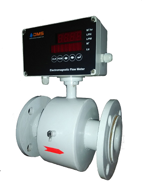
Electromagnetic flow meter can be used for precise flow measurement of all electrically conductive liquids such as sledges,
slurries, sewage, milk, water and waste water.
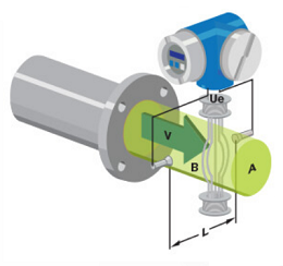

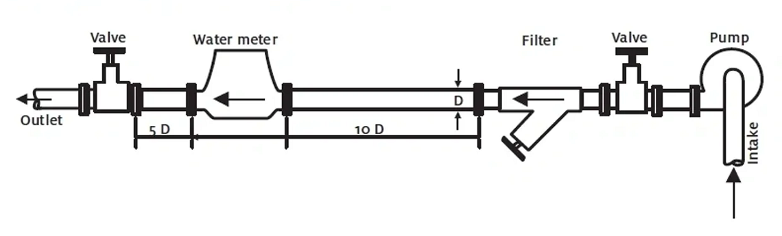
The Primary Flow Tube can be installed at any point in the pipe run either horizontal or vertical provided the following conditions are satisfy as per figure 1.1 / 1.2 / 1.3 do not install flow meter as per Figure 1.4
1) The direction of flow through the pipe is the same as indicated on the primary flow tube by a red arrow.
2) Straight lengths of 5D on upstream and 3D on downstream, measured from the Electrode axis is maintained.
3) If disturbances like cork screwing or vortex flow conditions are present straight lengths should be increased or flow straightness should be used. Flaps, slide gates, valves etc should be arranged at a distance of at least 3D downstream of primary flow tube.
4) Installations are as under


| Flow Rates with Velocity | ||||||
|---|---|---|---|---|---|---|
| METER SIZE | Flow Rates (in m3/hr) at different velocities | |||||
| Inch | DN | 1.00m/s | 1.25m/s | 2.50m/s | 5.00m/s | 10.00m/s |
| 0.5 | 15 | 0.636 | 0.795 | 1.59 | 3.18 | 6.36 |
| 0.75 | 20 | 1.131 | 1.41375 | 2.8275 | 5.655 | 11.31 |
| 1 | 25 | 1.767 | 2.20875 | 4.4175 | 8.835 | 17.67 |
| 1.25 | 32 | 2.895 | 3.61875 | 7.2375 | 14.475 | 28.95 |
| 1.5 | 40 | 11.95 | 14.9375 | 29.875 | 59.75 | 119.5 |
| 2 | 50 | 7.068 | 8.835 | 17.67 | 35.34 | 70.68 |
| 2.5 | 65 | 11.95 | 14.9375 | 29.875 | 59.75 | 119.5 |
| 3 | 80 | 18.907 | 23.63375 | 47.2675 | 94.535 | 189.07 |
| 4 | 100 | 28.2 | 35.25 | 70.5 | 141 | 282 |
| 5 | 125 | 44.18 | 55.225 | 110.45 | 220.9 | 441.8 |
| 6 | 150 | 63.62 | 79.525 | 159.05 | 318.1 | 636.2 |
| 8 | 200 | 113.1 | 141.375 | 282.75 | 565.5 | 1131 |
| 10 | 250 | 176.7 | 220.875 | 441.75 | 883.5 | 1767 |
| 12 | 300 | 254.5 | 318.125 | 636.25 | 1272.5 | 2545 |
| 14 | 350 | 346.4 | 433 | 866 | 1732 | 3464 |
| 16 | 400 | 452.4 | 565.5 | 1131 | 2262 | 4524 |
| 20 | 500 | 706.9 | 883.625 | 1767.25 | 3534.5 | 7069 |
| 24 | 600 | 1018 | 1272.5 | 2545 | 5090 | 10180 |
| 28 | 700 | 1385 | 1731.25 | 3462.5 | 6925 | 13850 |
| 32 | 800 | 1810 | 2262.5 | 4525 | 9050 | 18100 |
| 36 | 900 | 2290 | 2862.5 | 5725 | 11450 | 22900 |

| DN SIZE | METER SIZE | A (mm) | B (mm) | C (mm) | D (mm) | E (mm) | F (mm) | G (mm) | H (mm) |
|---|---|---|---|---|---|---|---|---|---|
| 6 | ?" | 88.9 | 130 | 84 | 200 | 34.9 | 35 | 100 | 80 |
| 10 | ?" | 88.9 | 130 | 84 | 200 | 34.9 | 35 | 100 | 80 |
| 15 | 1⁄2" | 88.9 | 130 | 84 | 200 | 34.9 | 35 | 100 | 80 |
| 20 | 3⁄4" | 98.4 | 130 | 84 | 200 | 42.9 | 35 | 100 | 80 |
| 25 | 1" | 107.9 | 130 | 84 | 200 | 50.8 | 35 | 100 | 80 |
| 32 | 11⁄4" | 117.5 | 130 | 84 | 200 | 63.5 | 35 | 100 | 80 |
| 40 | 11⁄2" | 127.0 | 130 | 84 | 200 | 73.0 | 35 | 100 | 80 |
| 50 | 2" | 152.4 | 156 | 84 | 200 | 92.1 | 35 | 100 | 80 |
| 65 | 21⁄2" | 177.8 | 184 | 84 | 200 | 104.8 | 35 | 100 | 80 |
| 80 | 3" | 190.5 | 195 | 84 | 200 | 127.0 | 35 | 100 | 80 |
| 100 | 4" | 228.6 | 233 | 115 | 235 | 157.2 | 35 | 100 | 80 |
| 125 | 5" | 254.0 | 258 | 120 | 235 | 185.7 | 35 | 100 | 80 |
| 150 | 6" | 279.4 | 284 | 120 | 240 | 215.9 | 35 | 100 | 80 |
| 200 | 8" | 342.9 | 348 | 150 | 290 | 269.9 | 35 | 100 | 80 |
| 250 | 10" | 406.4 | 412 | 200 | 390 | 323.8 | 35 | 100 | 80 |
| 300 | 12" | 482.6 | 490 | 250 | 490 | 381.0 | 35 | 100 | 80 |
| 350 | 14" | 533.4 | 540 | 300 | 540 | 412.7 | 35 | 100 | 80 |
| 400 | 16" | 596.9 | 603 | 340 | 590 | 469.9 | 35 | 100 | 80 |
| 450 | 18" | 635.0 | 641 | 340 | 590 | 533.4 | 35 | 100 | 80 |
| 500 | 20" | 698.5 | 706 | 340 | 590 | 584.2 | 35 | 100 | 80 |
| 600 | 24" | 812.8 | 820 | 400 | 650 | 692.1 | 35 | 100 | 80 |
| 700 | 28" | 925 | 935 | 430 | 700 | 798.0 | 35 | 100 | 80 |

| Flow Rates at Velocity | ||||||
|---|---|---|---|---|---|---|
| METER SIZE | Flow Rates (in m3/hr) at different velocities | |||||
| Inch | DN | 1.00m/s | 1.25m/s | 2.50m/s | 5.00m/s | 10.00m/s |
| 5 | 125 | 44.18 | 55.225 | 110.45 | 220.9 | 441.8 |
| 6 | 150 | 63.62 | 79.525 | 159.05 | 318.1 | 636.2 |
| 8 | 200 | 113.1 | 141.375 | 282.75 | 565.5 | 1131 |
| 10 | 250 | 176.7 | 220.875 | 441.75 | 883.5 | 1767 |
| 12 | 300 | 254.5 | 318.125 | 636.25 | 1272.5 | 2545 |
| 14 | 350 | 346.4 | 433 | 866 | 1732 | 3464 |
| 16 | 400 | 452.4 | 565.5 | 1131 | 2262 | 4524 |
| 20 | 500 | 706.9 | 883.625 | 1767.25 | 3534.5 | 7069 |
| 24 | 600 | 1018 | 1272.5 | 2545 | 5090 | 10180 |
| 28 | 700 | 1385 | 1731.25 | 3462.5 | 6925 | 13850 |
| 32 | 800 | 1810 | 2262.5 | 4525 | 9050 | 18100 |
| 36 | 900 | 2290 | 2862.5 | 5725 | 11450 | 22900 |

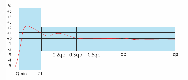

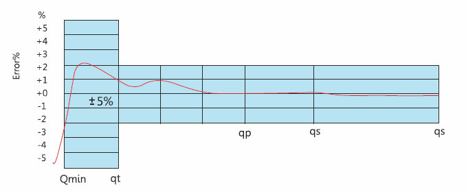
Indicating Error:
In the lower zone Qmin inclusive up to but excluding Qt is +5% In the Upper zone from Qt Inclusive up to & including Qs is +2%
Pressure Loss not to exceed : 0.1 Mpa at Qmax, 0.0025 Mpa at Qn
Working Conditions:
Water temperature:
Working Pressure: 1.6 Mpa
Maximum Test Pressure: 2.0 MPa
Product Features:


Indicating Error:
In the lower zone Qmin inclusive up to but excluding Qt is +5% In the Upper zone from Qt Inclusive up to & including Qs is +2%
Pressure Loss not to exceed : 0.1 Mpa at Qmax, 0.0025 Mpa at Qn
Working Conditions:
Water temperature:Working Pressure: 1.6 Mpa
Maximum Test Pressure: 2.0 MPa
Product Features:
